Module 1 Setup AVS Connectivity
Introduction Module 1
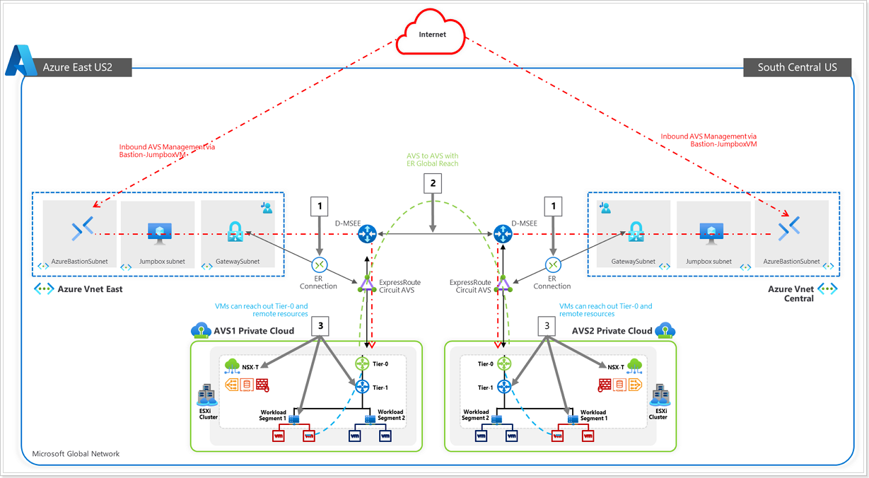
Azure VMware Solution offers a private cloud environment accessible from On-Premises and Azure-based resources. Services such as Azure ExpressRoute, VPN connections, or Azure Virtual WAN deliver the connectivity.
Scenario
Customer needs to have connectivity between their workloads in AVS, existing services and workloads in Azure, and access to the internet.
Connectivity Options for AVS
This hands-on lab will show you how to configure the Networking components of an Azure VMware Solution for:
- Connecting Azure VNet’s to AVS over an ExpressRoute circuit (Preconfigured).
- Peering with remote environments using Global Reach (Not Applicable in this lab).
- AVS Interconnect Options
- Configuring NSX-T (check DNS and configure DHCP, Segments, and Gateway) to manage connectivity within AVS.
The lab environment has a preconfigured Azure VMware Solution environment with an Express Route circuit. A nested or embedded VMware environment is configured to simulate an On-Premises environment (PLEASE DO NOT TOUCH).
Both environments are accessible through JumpBox VM that you can deploy in Azure. You can RDP to Jumpbox through a preconfigured Azure Bastion service.
After this lab is complete, you will have built out this scenario below:
- ExpressRoute, for connectivity between Azure VMware Solution and Azure Virtual Networks.
- Configure NSX-T to establish connectivity within the AVS environment.
- Creation of Test VMs to attach to your NSX-T Network Segments.
- Explore some advanced NSX-T features like tagging, creation of groups, Distributed Firewall Features.
1 - Module 1 Task 1
Task 1 - AVS Connectivity Options
AVS Connectivity Options
THIS IS FOR REFERENCE ONLY AS IT HAS BEEN PRECONFIGURED FOR THIS LAB.
Section Overview
In this section you will create a connection between an existing, non-AVS,
Virtual Network in Azure and the Azure VMware Solution environment. This allows
the jumpbox virtual machine you created to manage key components in the VMware management
plane such as vCenter, HCX, and NSX-T. You will also be able to access Virtual
Machines deployed in AVS and allow those VMs to access resources deployed in
the Hub or Spoke VNet’s, such as Private Endpoints and other Azure VMs or
Services.

Summary: Generate a new Authorization Key in the AVS ExpressRoute settings,
and then create a new Connection from the Virtual Network Gateway in the VNet
where the JumpBox is connected to.
The diagram below shows the respective resource groups for your lab environment.
You will replace Name with Partner Name, for example: GPSUS-Name1-SDDC for partner XYZ would be GPSUS-XYZ1-SDDC.

Option 1: Internal ExpressRoute Setup from AVS -> VNet
NOTE:
- Since we already have a virtual network gateway, you’ll add a connection between it and your Azure VMware Solution private cloud.
- The last step of this section is expected to fail, the Connection will be created but it will be in Failed state because another Connection to the same target already exists. This is expected behavior and you can ignore the error.
Step1: Request an ExpressRoute authorization key

In your AVS Private Cloud:
- Click Connectivity.
- Click ExpressRoute tab.
- Click + Request an authorization key.
Step 2: Name Authorization Key

- Give your authorization key a name: group-XY-key, where X is your group number, and Y is your participant number.
- Click Create. It may take about 30 seconds to create the key. Once created, the new key appears in the list of authorization keys for the private cloud.
Copy the authorization key and ExpressRoute ID and keep it handy. You will need them to complete the peering. The authorization key disappears after some time, so copy it as soon as it appears.
Step 3: Create connection in VNet Gateway

- Navigate to the Virtual Network Gateway named GPSUS-Name#-Network where # is your group number.
- Click Connections.
- Click + Add.
Step 4: Establish VNet Gateway Setup

Enter a Name for your connection. Use GROUPXY-AVS where X is your group number and Y is your participant number.
For Connection type select ExpressRoute.
Ensure the checkbox next to “Redeem authorization” is selected.
Enter the Authorization key you copied earlier.
For Peer circuit URI paste the ExpressRoute ID you copied earlier.
Click OK.
The connection between your ExpressRoute circuit and your Virtual Network is
created.
Reminder: It is expected that the connection is in Failed State after
the creation, that is because another connection to the same target already
exists. Next, delete the connection.
Step 5: Delete connection

- Navigate to your Virtual Network Gateway named **GPSUS-NameX-GW where X is your group number.
- Click Connections.
- Select the 3 ellipses next to the connection with the status of Failed and select Delete.
Option 2: ExpressRoute Global Reach Connection from AVS -> Customer’s on-premises ExpressRoute

ExpressRoute Global Reach connects your on-premises environment to your Azure VMware Solution private cloud. The ExpressRoute Global Reach connection is established between the private cloud ExpressRoute circuit and an existing ExpressRoute connection to your on-premises environments. Click here for more information.
Step 1: ExpressRoute Circuits in Azure Portal
NOTE: There are no ExpressRoute circuits setup in this environment. These steps are informational only.

- In the Azure Portal search bar type ExpressRoute.
- Click ExpressRoute circuits.
Step 2: Create ExpressRoute Authorization

- From the ExpressRoute circuits blade, click Authorizations.
- Give your authorization key a Name.
- Click Save. Copy the Authorization Key created and keep it handy.
- Also copy the Resource ID for the ExpressRoute circuit and keep it handy.
Step 3: Create Global Reach Connection in AVS

- From your AVS Private Cloud blade, click Connectivity.
- Click ExpressRoute Global Reach.
- Click + Add.
- In the ExpressRoute circuit box, paste the Resource ID copied in the previous step.
- Paste the Authorization Key created in the previous step.
- Click Create.
Option 3: AVS Interconnect
The AVS Interconnect feature lets you create a network connection between two or more Azure VMware Solution private clouds located in the same region. It creates a routing link between the management and workload networks of the private clouds to enable network communication between the clouds. Click here for more information.
Step 1: Establish AVS Interconnect in your AVS SDDC

- In your AVS Private Cloud blade, click Connectivity.
- Click AVS Interconnect.
- Click + Add.
Step 2: Add connection to another private cloud

- Subscription and Location are automatically populated based on the values of your Private Cloud, ensure these are correct.
- Select the Resource group of the other Private Cloud you would like to connect to.
- Select the AVS Private cloud you wish to connect.
- Ensure the checkbox next to “I confirm that the two private clouds to be connected don’t contain overlapping network address space”.
- Click Create.
It takes a few minutes for the connection to complete. Once completed the networks found in both Private Clouds will be able to talk to each other. Feel free to perform this exercise if no one in your group has done it as there is a requirement to connect a second Private Cloud in order to perform the exercises in Module 3 (Site Recovery Manager).
Confirm access from Jumpbox
You can now validate access to your Azure VMware Solution components like vCenter and NSX-T from the Jumpbox you created.
Step 1: Obtain AVS Login Credentials

- Navigate to the Azure VMware Solution blade associated with your group: GPSUS-Name#-SDDC.
- Click your assigned AVS SDDC.
- Click Identity.
- You will now see the Login Credentials for both vCenter and NSX-T. You will need these credentials for the next few steps. You do not need to copy the Certificate thumbprint.
PLEASE DO NOT GENERATE A NEW PASSWORD.
Step 2: Access AVS from Jumpbox

Click Connect and Bastion from the previously created Jumpbox blade.

Once connected to your Jumpbox, open a browser and enter the IP Address for AVS vCenter located in a previous step. There might be a secure browser connection message. Click the advanced button and select the option to continue. Then click on LAUNCH VSPHERE CLIENT (HTML 5).

If the VMware vSphere login page launches successfully, then everything is working as expected.
You’ve now confirmed that you can access AVS from a remote environment
References
Tutorial - Configure networking for your VMware private cloud in Azure - Azure
VMware Solution | Microsoft
Docs
2 - Module 1 Task 2
Task 2: Configure NSX-T to establish connectivity within AVS
NSX-T on AVS
After deploying Azure VMware Solution, you can configure an NSX-T network
segment from NSX-T Manager or the Azure portal. Once configured, the segments
are visible in Azure VMware Solution, NSX-T Manager, and vCenter.
NSX-T comes pre-provisioned by default with an NSX-T Tier-0 gateway in
Active/Active mode and a default NSX-T Tier-1 gateway in Active/Standby mode.
These gateways let you connect the segments (logical switches) and provide
East-West and North-South connectivity. Machines will not have IP addresses
until statically or dynamically assigned from a DHCP server or DHCP relay.
In this Section, you will learn how to:
Create additional NSX-T Tier-1 gateways.
Add network segments using either NSX-T Manager or the Azure portal
Configure DHCP and DNS
Deploy Test VMs in the configured segments
Validate connectivity

In your Jumpbox, open a browser tab and navigate to the NSX-T URL found in the AVS Private Cloud blade in the Azure Portal. Login using the appropriate credentials noted in the Identity tab.
NOTE: This task is done by default for every new AVS deployment
AVS DNS forwarding services run in DNS zones and enable workload VMs in the zone
to resolve fully qualified domain names to IP addresses. Your SDDC includes
default DNS zones for the Management Gateway and Compute Gateway. Each zone
includes a preconfigured DNS service. Use the DNS Services tab on the DNS
Services page to view or update properties of DNS services for the default
zones. To create additional DNS zones or configure additional properties of DNS
services in any zone, use the DNS Zones tab.
The DNS Forwarder and DNS Zone are already configured for this training but
follow the steps to see how to configure it for new environments.

- Ensure the POLICY view is selected.
- Click Networking.
- Click DNS.
- Click DNS Services.
- Click the elipsis button -> Edit to view/edit the default DNS settings.

- Examine the settings (do not change anything) and click CANCEL.
Exercise 2: Add DHCP Profile in AVS Private Cloud
Please ensure to replace X with your group’s assigned number, Y with your participant number. For participant 10 please replace XY with 20
| AVS NSX-T Details | |
|---|
| DHCP Server IP | 10.XY.50.1/30 |
| Segment Name | WEB-NET-GROUP-XY |
| Segment Gateway | 10.XY.51.1/24 |
| DHCP Range | 10.XY.51.4-10.XY.51.254 |
A DHCP profile specifies a DHCP server type and configuration. You can use the
default profile or create others as needed.
A DHCP profile can be used to configure DHCP servers or DHCP relay servers
anywhere in your SDDC network.
Step 1: Add DHCP Profile

- In the NSX-T Console, click Networking.
- Click DHCP.
- Click ADD DHCP PROFILE.

- Name the profile as DHCP-Profile-GROUP-XY-AVS for your respective group/participant.
- Ensure DHCP Server is selected.
- Specify the IPv4 Server IP Address as 10.XY.50.1/30 and optionally change the Lease Time or leave the default.
- Click SAVE.
Exercise 3: Create an NSX-T T1 Logical Router
NSX-T has the concept of Logical Routers (LR). These Logical Routers can perform both distributed or centralized functions. In AVS, NSX-T is deployed and configured with a default T0 Logical Router and a default T1 Logical Router.
The T0 LR in AVS cannot be manipulated by AVS customers, however the T1 LR can be configured however an AVS customer chooses. AVS customers also have the option to add additional T1 LRs as they see fit.

Step 1: Add Tier-1 Gateway

- Click Networking.
- Click Tier-1 Gateways.
- Click ADD TIER-1 GATEWAY.

- Give your T1 Gateway a Name. Use GROUP-XY-T1.
- Select the default T0 Gateway, usually TNT**-T0.
- Click SAVE. Clck NO to the question “Want to continue configuring this Tier-1 Gateway?”.
Exercise 4: Add the DHCP Profile to the T1 Gateway

- Click the elipsis next to your newly created T1 Gateway.
- Click Edit.
Step 1: Set DHCP Configuration to Tier-1 Gateway

- Click Set DHCP Configuration.
- After finishing the DHCP Configuration, click to expand Route Advertisement and make sure all the buttons are enabled.

- Ensure DHCP Server is selected for Type.
- Select the DHCP Server Profile you previously created.
- Click SAVE. Click SAVE again to confirm changes, then click CLOSE EDITING.
Exercise 5: Create Network Segment for AVS VM workloads
Network segments are logical networks for use by workload VMs in the SDDC
compute network. Azure VMware Solution supports three types of network segments:
routed, extended, and disconnected.
A routed network segment (the default type) has connectivity to other
logical networks in the SDDC and, through the SDDC firewall, to external
networks.
An extended network segment extends an existing L2VPN tunnel, providing a
single IP address space that spans the SDDC and an On-Premises network.
A disconnected network segment has no uplink and provides an isolated
network accessible only to VMs connected to it. Disconnected segments are
created when needed by HCX. You can also create them yourself and can
convert them to other segment types.
Step 1: Add Network Segment

- Click Networking.
- Click Segments.
- Click ADD SEGMENT.

- Enter WEB-NET-GROUP-XY in the Segment Name field.
- Select the Tier-1 Gateway you created previously (GROUP-XY-T1) as the Connected Gateway.
- Select the pre-configured overlay Transport Zone (TNTxx-OVERLAY-TZ).
- In the Subnets column, you will enter the IP Address for the Gateway of the Subnet that you are creating, which is the first valid IP of the Address Space.
- For Example: 10.XY.51.1/24
- Then click SET DHCP CONFIG.
Step 3: Set DHCP Configuration on Network Segment

- Ensure Gateway DHCP Server is selected for DHCP Type.
- In the DHCP Config click the toggle button to Enabled.
- Then in the DHCP Ranges field enter the range according to the IPs assigned to your group. The IP in in the same network as the Gateway defined above.
- Use 10.XY.51.4-10.XY.51.254
- In the DNS Servers, enter the IP 1.1.1.1.
- Click Apply. Then SAVE and finally NO.
Important
The IP address needs to be on a non-overlapping RFC1918 address block, which ensures connection to the VMs on the new segment.
References
3 - Module 1 Task 3
Create Test VMs and connect to Segment
Create Test VMs
Now that we have our networks created, we can deploy virtual machines and ensure we can get an IP address from DHCP. Go ahead and Login into your AVS vCenter.
Exercise 1: Create a content Library
Step 1: Create vCenter Content Library

- From AVS vCenter, click the Menu bars.
- Click Content Libraries.

Click CREATE
Step 2: Give your Content Library a Name and Location

- Name your Library LocalLibrary-XY where X is your group number and Y is your participant number
- Click NEXT
- Leave the defaults for Configure content library and for Appy security policy
Step 3: Specify Datastore for Content Library

- For Add storage select thevsanDatastore
- Click NEXT then FINISH
Exercise 2: Import Item to Content Library
Step 1: Import OVF/OVA to Content Library

- Click on your newly created Library and click Templates.
- Click OVF & OVA Templates
- Click ACTIONS
- Click Import item
Step 2: Specify URL for OVF/OVA

Import using this URL - Download Link
https://gpsusstorage.blob.core.windows.net/ovas-isos/workshop-vm.ova
This will now download and import the VM to the library
Exercise 3: Create VMs
Step 1: Create VM from Template

Once downloaded, Right-click the VM Template > New VM from This Template.
Step 2: Select a Name and Folder for the VM

- Give the VM a name – e.g VM1-AVS-XY
- Select the SDDC-Datacenter
- Click NEXT
Step 3: Select a Compute Resource

- Select Cluster-1
- Click NEXT
Step 4: Review Details, select Datastore

- Review Details and click NEXT. Accept the terms and click NEXT
- Confirm the storage as the vsanDatastore
- Click NEXT
Step 5: Select network for VM

Select the segment that you created previously- “WEB-NET-GROUP-XY” and click NEXT. Then review and click FINISH.
Once deployed, head back to VM’s and Templates and Power On this newly created VM. This VM is provided as a very lightweight Linux machine that will automatically pick up DHCP if configured. Since we have added this to the WEB-NET-GROUP-XY segment, it should get an IP address from this DHCP range. This usually takes few seconds. Click the “Refresh” button on vCenter toolbar.
If you see an IP address here, we have successfully configured the VM and it has connected to the segment and will be accessible from the Jumpbox.
We can confirm this by SSH’ing to this IP address from the Jumpbox.
Username: root
Password: AVSR0cks!
YOU MAY BE ASKED TO CHANGE THE PASSWORD OF THE ROOT USER ON THE VM, CHANGE IT TO A PASSWORD OF YOUR CHOOSING, JUST REMEMBER WHAT THAT PASSWORD IS.
Once you SSH into the VMs, enter these 2 commands to enable ICMP traffic on the VM:
iptables -A OUTPUT -p icmp -j ACCEPT
iptables -A INPUT -p icmp -j ACCEPT
PLEASE REPEAT THESE STEPS AND CREATE A SECOND VM CALLED ‘VM2-AVS-XY’
4 - Module 1 Task 4
Task 4: Advanced NSX-T Features within AVS
Section Overview:
You can find more information about NSX-T capabilities in VMware’s website under VMware NSX-T Data Center Documentation.
In this Section, you will learn just a few additional NSX-T Advanced Features. You will learn how to:
Create NSX-T tags for VMs
Create NSX-T groups based on tags
Create Distributed Firewall Rules in NSX-T
NSX-T Tags help you label NSX-T Data Center objects so that you can quickly search or filter objects, troubleshoot and trace, and do other related tasks.
You can create tags using both the NSX-T UI available within AVS and APIs.
More information on NSX-T Tags can be found here: VMware NSX-T Data Center Documentation.
Two Test VMs required
Please make sure that you have created 2 Test VMs as explained in the previous Task before you proceed in this exercise.
- From the NSX-T UI, click Inventory.
- Click Virtual Machines.
- Locate your 2 Virtual Machines you created in the previous task, notice they have no tags.
Click the elipsis next to the first VM and click Edit.
Step 2: Name your VM’s tag
- Type “GXY”, where X is your group number and Y is your participant number.
- Click to add GXY as a tag to this VM.
- Click SAVE.
REPEAT THE ABOVE STEPS FOR VM2 USING THE SAME TAG.
NSX-T Groups
Groups include different objects that are added both statically and dynamically, and can be used as the source and destination of a firewall rule.
Groups can be configured to contain a combination of Virtual Machines, IP sets, MAC sets, segment ports, segments, AD user groups, and other groups. Dynamic including of groups can be based on a tag, machine name, OS name, or computer name.
You can find more information on NSX-T Groups on VMware’s NSX-T Data Center docs.
Exercise 2: Create NSX-T Groups
Step 1: Create an NSX-T Group
Now that we’ve assigned tags to the VMs, we’ll create a group based of those tags.
- Click Inventory
- Click Groups
- Click ADD GROUP
Step 2: Name your NSX-T Group and Assign Members
- Name your group GROUP-XY where X is your group number and Y is your participant number
- Click on *Set Members
Step 3: Set the Membership Criteria for your Group
- Click ADD CRITERIA
- Select Virtual Machine
- Select Tag
- Select Equals
- Select your previously created group GXY
- Click APPLY. Then click SAVE
NSX-T Distributed Firewall
NSX-T Distributed Firewall monitors all East-West traffic on your AVS Virtual Machines and allows you to either deny or allow traffic between these VMs even if the exist on the same NSX-T Network Segment. This is the example of your 2 VMs and we will assume they’re 2 web servers that should never have to talk to each other. More information can be found here: Distributed Firewall.
Exercise 3: Create an NSX-T Distributed Firewall Policy
Step 1: Add a Policy
- Click Security
- Click Distributed Firewall
- Click + ADD POLICY
- Give your policy a name “Policy XY” where X is your group number and Y is your participant number
- Click the elipsis and select Add Rule
Step 2: Add a Rule
- Name your rule “Rule XY”
- Click under Sources column and select your newly created “GROUP-XY”
- Click under Destinations and also select “GROUP-XY”
- Leave all other defaults, and for now, leave the Action set to Allow. We will change this later to understand the behavior
- Click PUBLISH to publish the newly created Distributed Firewall Rule
Step 3: Reject communication in your Distributed Firewall Rule
Hopefully you still have the SSH sessions open to your 2 VMs you created earlier. If not, just SSH again. From one of the VMs, run a continuous ping to the other VM’s IP address like the example below.
- Change the Action in your Rule to Reject
- Click PUBLISH

You can notice that after publishing the change to Reject on your rule, the ping now displays “Destination Host Prohibited”. NSX-T DFW feature is allowing the packet to get from one VM to another but it rejects it once the second VM receives the packet. You can also change this option to Drop where the packet is completely dropped by the second VM.